All-Purpose Scout 80 Build

MotoDave

Adventurist
Founding Member
I spent a couple of years building and wheeling my daily driver Toyota T100, and while fun at first I definitely found the wear and tear on the daily driver to be a drag. Not to mention the more I modified the truck, the more it sucked for on-road duties, as I’m sure most here know. I’ve always liked building things myself, so I started looking for a project that I could really get into and build as much as possible myself. I’m a mechanical engineer by trade, and find fabrication and welding to be a really enjoyable change from flying a workstation all day.

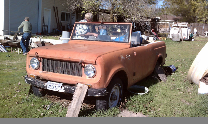
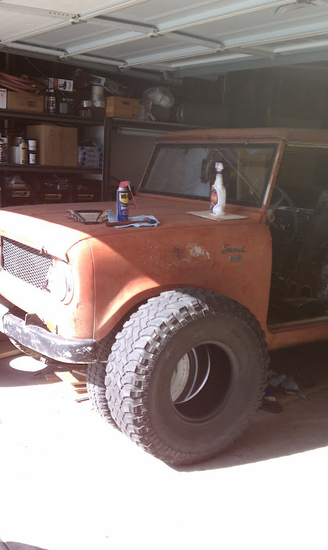
I bought this 1962 Scout 80 on Christmas day in 2010, from a family friend who was clearing out a collection of cars in preparation for a move. He has had it for 15+ years used as a utility truck to move cars around his property. My brother in law and the owner’s son both learned to drive in the truck.

My wife didn’t agree with me that this was all the Christmas present we needed.
IMAG0060.jpg

IMAG0055.jpg


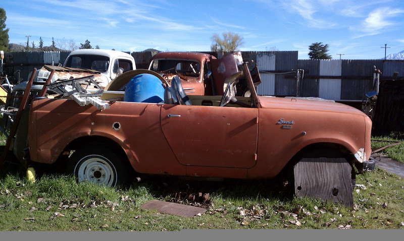
I brought home in March 2011, and it sat for the better part of a year while I figured out exactly what I wanted to build, and collected parts.

The truck was complete when I brought it home, but had not run in ~10 years. I think the previous owner would have preferred that I rebuild it, but I wanted to build the truck with modern drivetrain, to be fairly trail capable but still comfortable enough to drive to and from the trails.

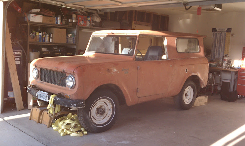
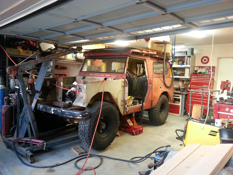
Hmm, the garage hasn’t looked this clean in a while ...
IMAG0108.jpg


Specs (subject to change whenever my upgrade-itis kicks in)
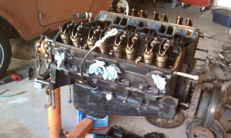
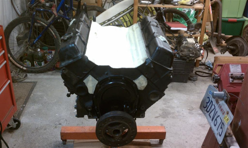
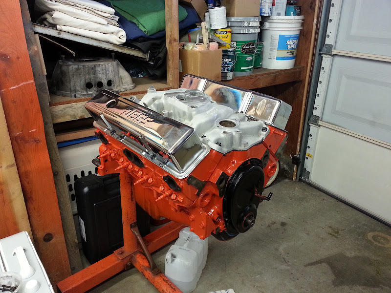
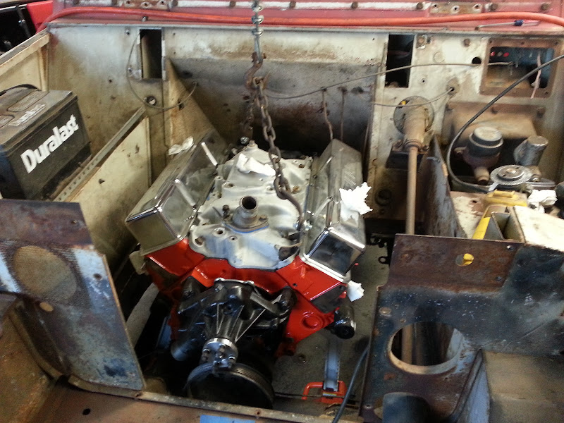
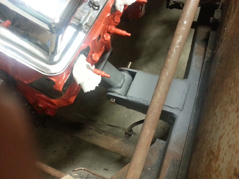
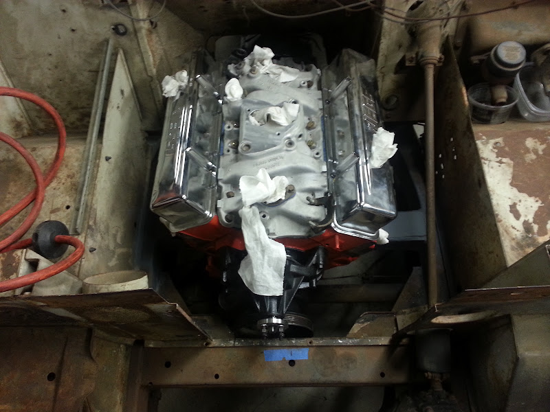
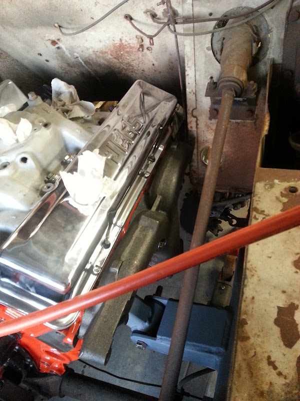
  • Chevy 350 w/ TBI fuel injection
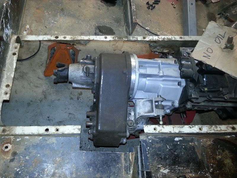
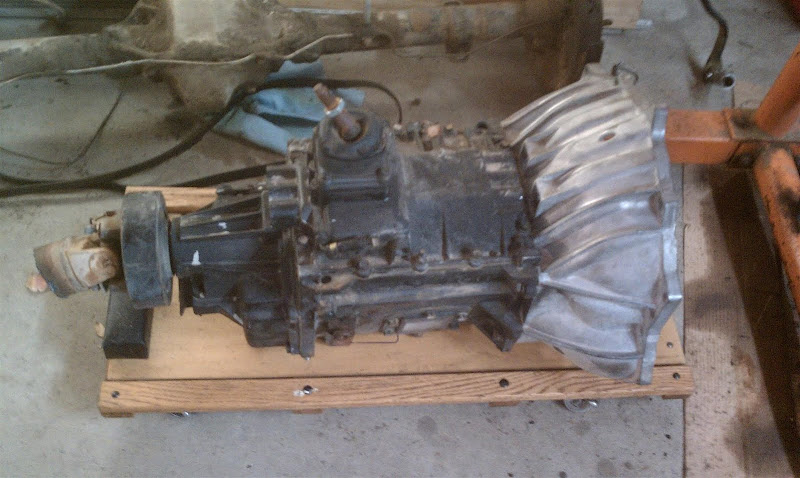
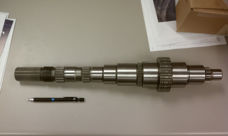
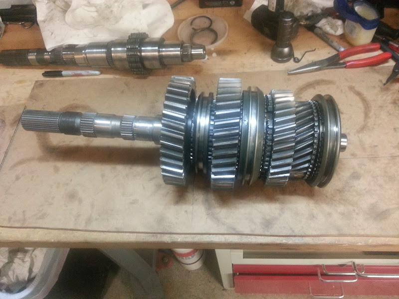
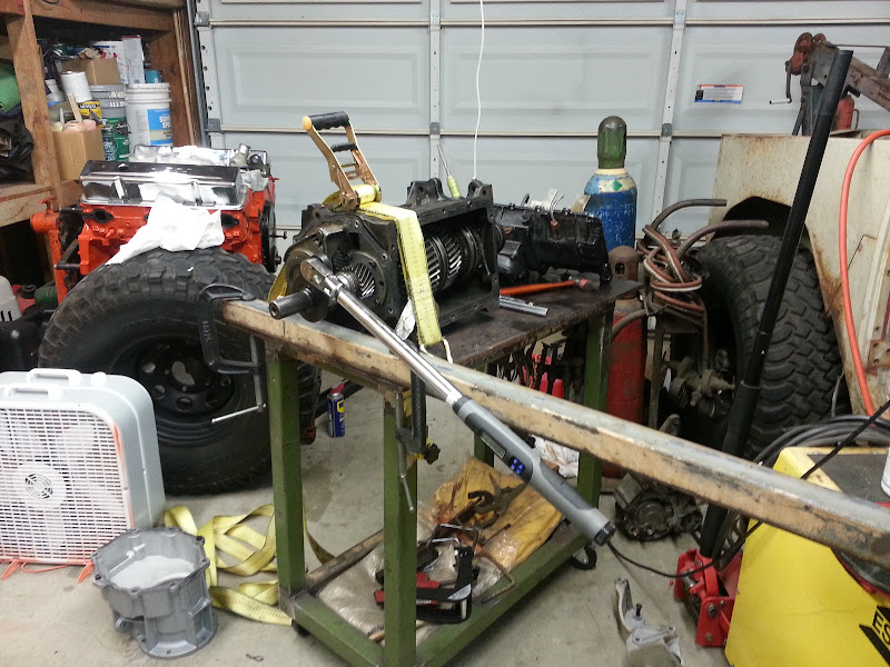
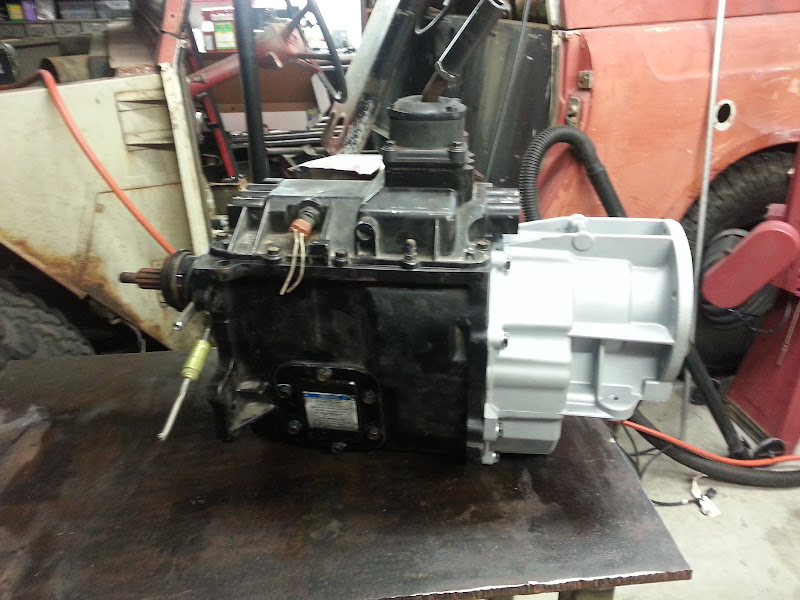
  • Chevy NV4500, converted from 2wd to 4wd
  • Jeep Dana 300, w/ 32 spline input shaft (advance adapters)
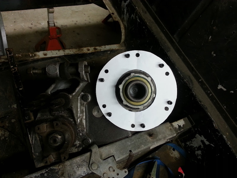
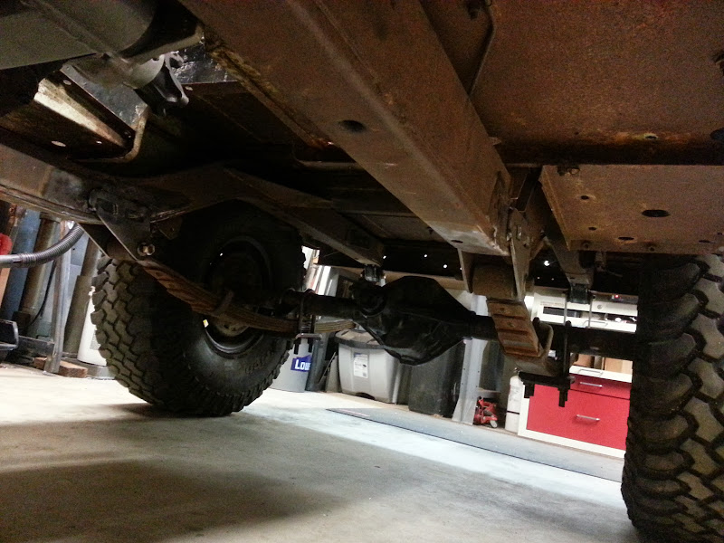
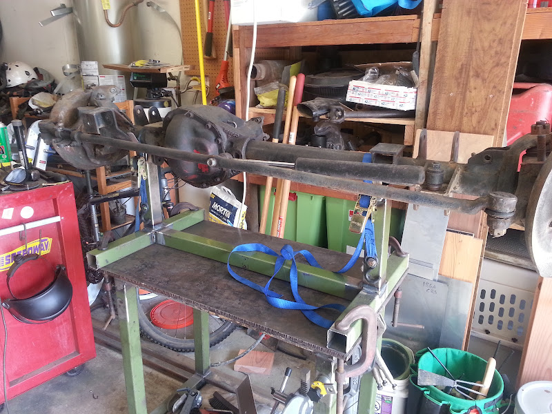
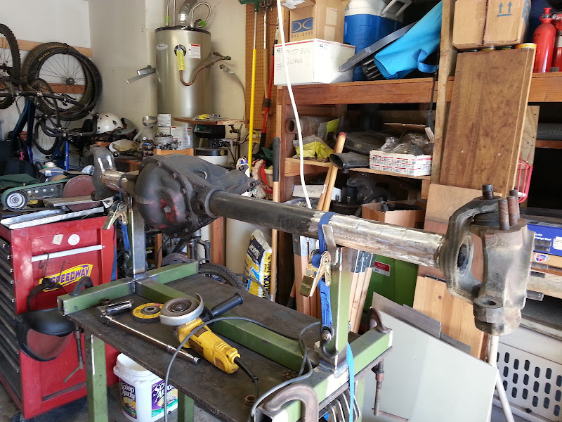
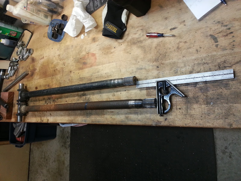
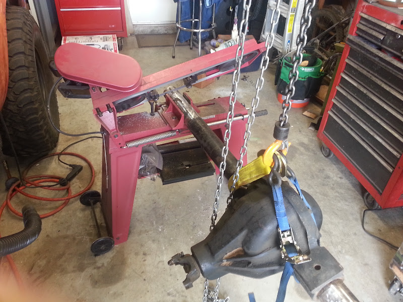
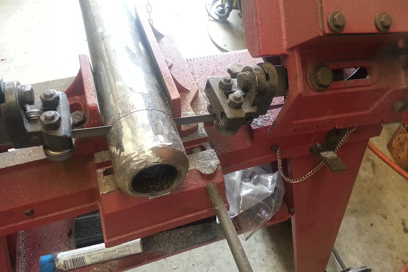
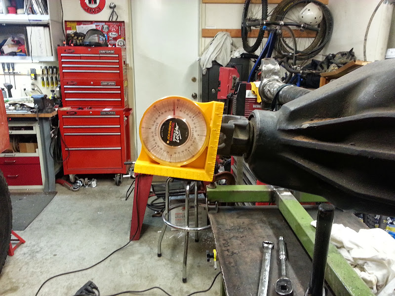
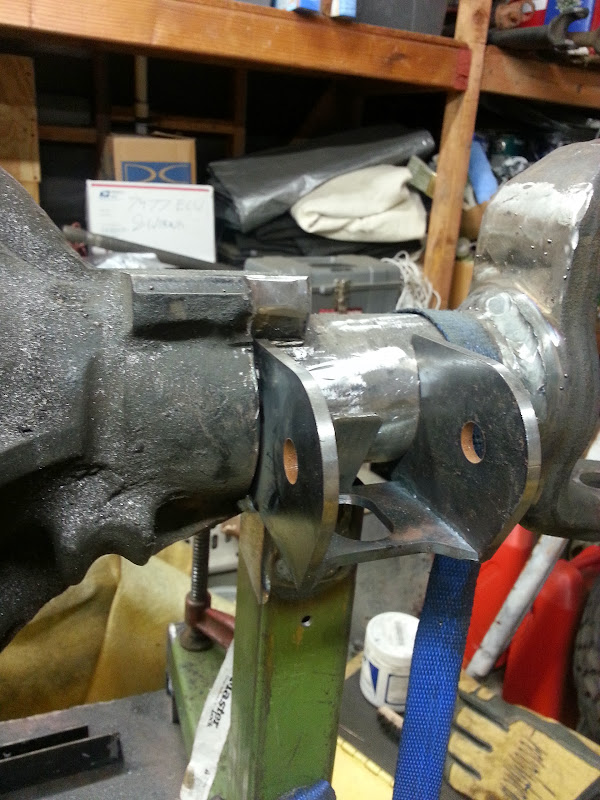
  • Front Axle: Chevy Blazer Dana 44, Ford hubs and rotors. Narrowed to Scout II width to be able to use Scout II axle shafts.
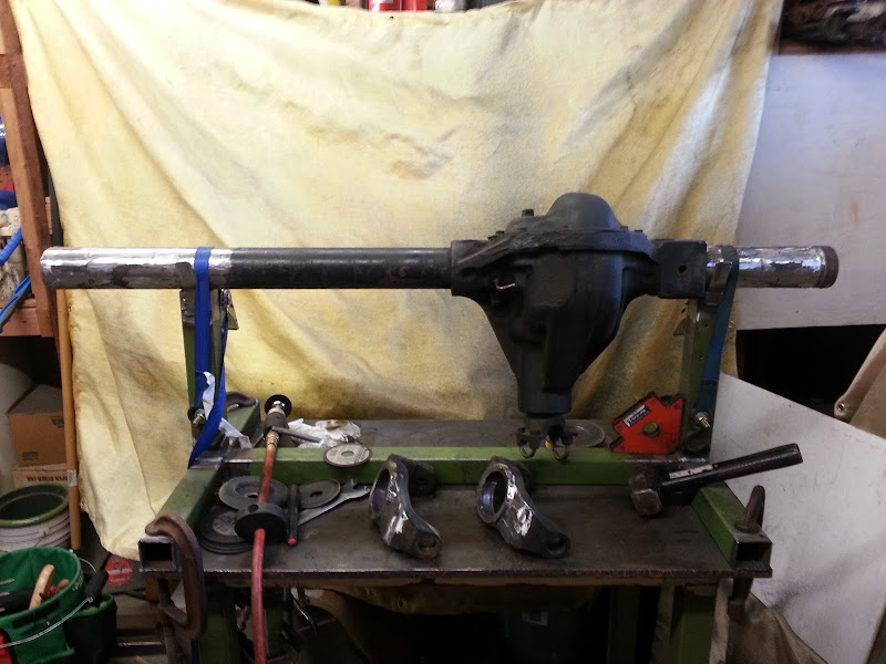
  • Rear Axle: Scout II Dana 44.
  • Gearing: 4.56 all around. Detroit locker in rear, ARB air locker in front
  • Tires: 35 x 12.5 x 15 BFG Mud Terrain
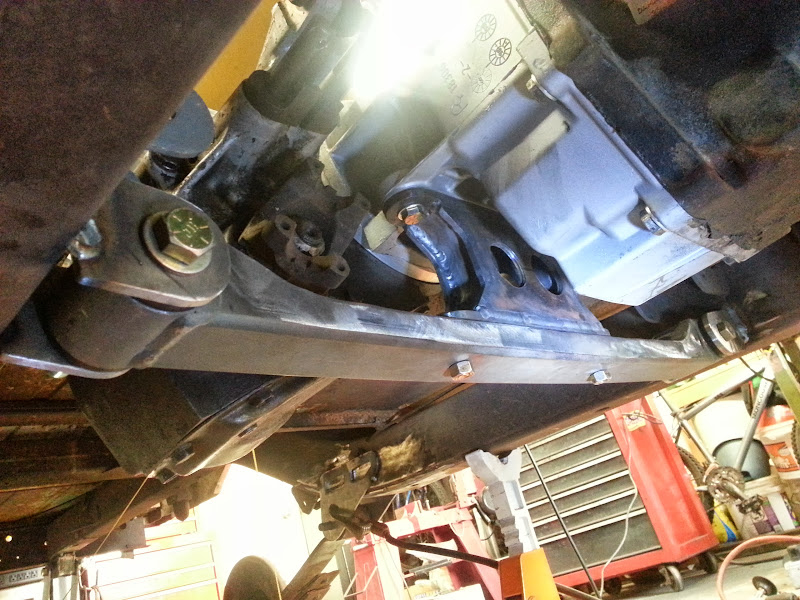
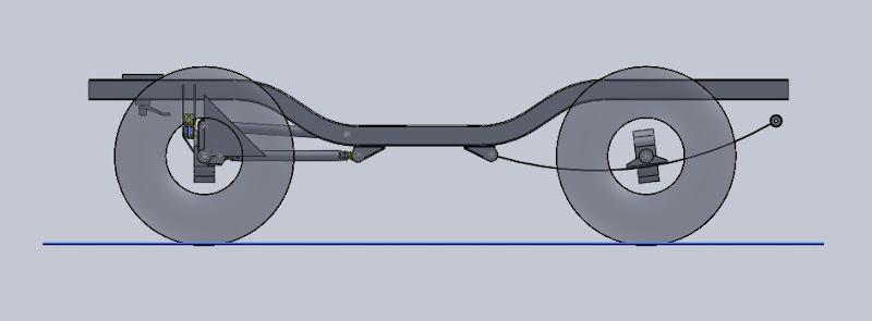
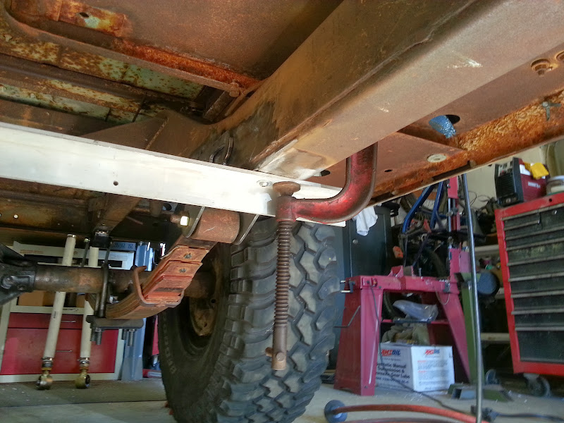
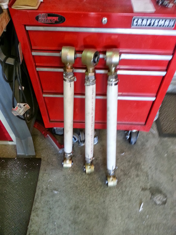
  • Front Suspension : 3 link with coilovers
  • Rear Suspension: 56” chevy leaf springs

This won’t be a fast build, but I’m hoping I’m to a point where I have the major parts collected and/or figure out, and will be able to update this often enough to keep it interesting.
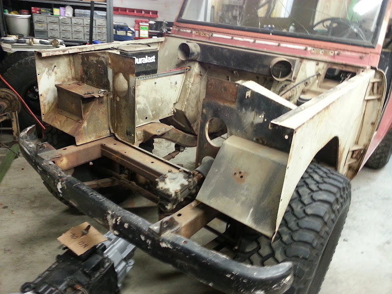
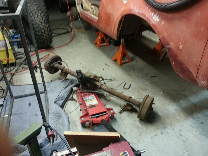
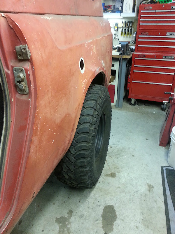
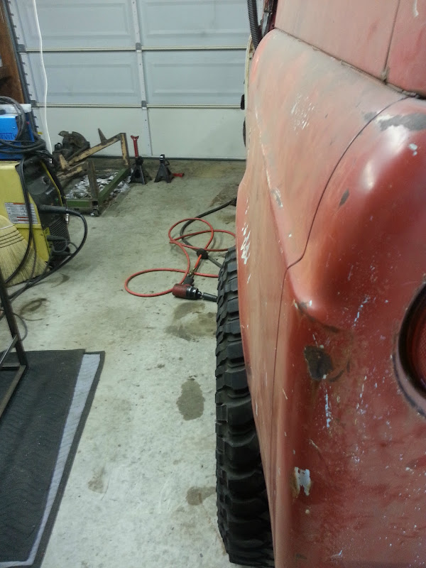
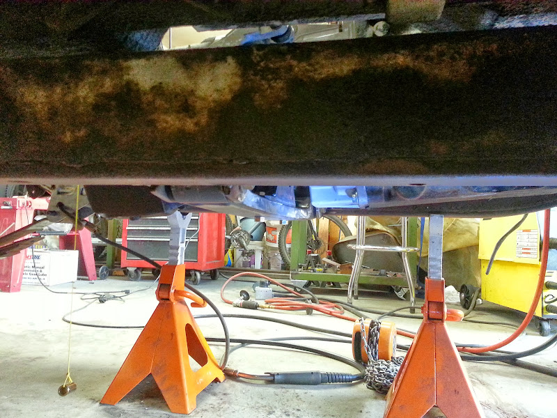
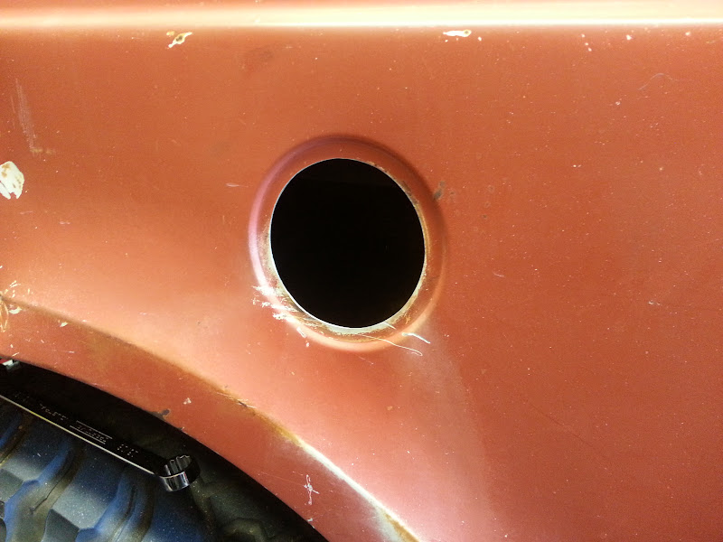
 
I really debated back and forth about what to power the scout with. I am a huge fan of small turbodiesel engines, so initially I was looking for a Cummins 4BT or Isuzu 4BD engine. I didn’t have much luck finding one of those either locally or at a price I could afford, so I decided to go with the old standard, a Chevy 350 V8 with TBI fuel injection. I ended up finding one up in Fresno at a good price, the only catch being I had to drive up, pull the engine, and drive back in a day. I managed to get it done, but damn that was a long day.
IMAG0154%2520%2528Large%2529.jpg


I really had no clue what shape the engine was in since the truck wasn’t running, but for the price it was worth it just for the TBI setup. I pulled the heads and oil pan, and nothing looked too bad. Wound up just replacing the gaskets throughout and buttoning it back up. Replaced the oil pump while I was at it, and shot it with some chevy orange paint, because secretly I’ve always wanted a shiny orange V8 engine 
IMAG0275%2520%2528Large%2529.jpg

2012-11-04%252012.21.32.jpg


I knew I wanted a manual transmission, and I knew in order to make this a dual use trail and street truck I’d want something with an overdrive. A bit of research pointed me to the NV4500 5 speed transmission, and I was able to pick up a used one out of a 90’s chevy 1 ton truck.
IMAG0195%2520%2528Large%2529.jpg


These transmissions have become pretty popular lately and the 4wd versions are getting pricy. I found a decent deal on one that was local to me, only catch being that it was the 2wd version. I found the parts needed to convert it to 4wd on ebay (mainshaft and tailhousing), and set about swapping the parts over. The mainshaft is maybe the most comically large machined piece I’ve ever worked with. No, that’s not a tiny pencil.
IMAG0198.jpg


I picked up a small parts kit from www.quad4x4.com, including new snap rings and a shim set. I also bought their NV4500 rebuild manual, which is definitely worthwhile if you’re considering rebuilding one of these. The mainshaft swap wasn’t too bad, you can leave the countershaft in the case as shown in this how-to. A couple of special tools were required, I had to get a bit creative with pullers to get 5th gear and the speedometer tone ring off of the mainshaft.

2012-11-06%252019.50.35.jpg


All the parts swapped onto the new mainshaft (old one in the background)
2012-11-08%252006.07.27.jpg


I also had to strap the tranny case to my welding table and clamp a 6’ piece of tube to the table, in order to be able to torque the 5th gear nut to 250-325 lb-ft with the special socket.

2012-11-12%252019.34.58.jpg


Done
2012-11-11%252017.26.33.jpg


The engine I bought came hooked to an automatic transmission, so I bought a flywheel and clutch kit. I’ve been told it’s a good idea to have the new flywheel match balanced to the old flex-plate, but I’ve yet to find a shop locally to do the work.

I pieced together a set of 35x12.5x15’s, which is the size I intend to run. The guys I wheel with are mostly on 33’s and 35’s, and I feel like it’s a good compromise between highway drivability, trail capability (and keeping the Dana 44’s alive). They’re just a tad larger than stock.

IMAG0199.jpg
 
A buddy of mine came down for a weekend, the original plan was to shoot some sporting clays, but we got rained out. Yes, it rains sometimes in SoCal. Anyways I put him to work, and we pulled the stock 4 cylinder out of the scout with no drama. There is a decent amount of room in the engine bay.
2012-12-18%252020.51.18.jpg


I built some engine mounts, and got the new engine and tranny roughly into place
2012-12-26%252014.06.17.jpg


2012-12-26%252017.00.23.jpg


Once the engine was where I thought it worked best, I tacked the motor mounts into place, then boxed them in. Not my best welds, as you’ll see later these get rebuilt after I got sick of looking at my ****ty welding for a while.

2012-12-28%252011.56.55.jpg


2012-12-29%252017.06.50.jpg


The Engine is as far back as I could get it, while keeping reasonable clearance for the exhaust manifolds. I’ll have to trim the firewall above the throttle pedal, but other than that it sits well.

2012-12-29%252017.06.36.jpg


2012-12-29%252017.07.09.jpg


I’m using corvette style exhaust manifolds, they do a good job of keeping everything tucked in close.

2013-01-08%252020.57.31.jpg


The manifold actually clears the firewall, but you can’t get a wrench on the bolt.

2013-02-20%252017.42.20.jpg


Around this time my wife and I went through some really rough times due to some personal matters. I also turned 30 and felt like cheering myself up, so I pre-built the Scout in Lego format.

20130107_081906%255B1%255D.jpg

20130107_081913%255B1%255D.jpg
 
Oops, stock axle (Dana 27) fell out.
2013-02-20%252018.15.45.jpg


I’m using a stock width Scout II rear Dana 44. Threw the wheels and tires on to see how the width looks on the narrower Scout 80 body. I like it 
2013-03-05%252019.51.55.jpg


Am I getting this stance thing right?
2013-03-05%252019.52.20.jpg


The rear end sat higher than I wanted with the springs over the axle, so I flipped the setup around and am running SUA. For now I am using 56” chevy springs, with a few leaves removed. I anticipate needing to tune this once the truck is on all four wheels again.
I used the CAD (Cardboard Aided Design) method to make some rear spring hangers.
2013-05-21%252019.59.51.jpg


2013-05-21%252020.49.22.jpg


2013-06-02%252019.12.40.jpg


Shackle hangers were more of a ‘cut and see if it works’ approach.
2013-07-11%252018.31.39.jpg


2013-07-14%252012.27.36.jpg


Rear end sitting on the new springs for the first time
2013-10-03%252019.40.19.jpg


2013-10-03%252019.40.27.jpg
 
Front axle is out of a Blazer, narrowed to use Scout II inner axle shafts. The main downside I see is the passenger side tube ends up really short. I’m going to cut down the leaf spring pad, and see if I can make it work, otherwise I may look for another axle or retube this one. Trying to stick with axles from a standard application so that spares are easier to source.

Note to self: Axles are heavy. Be careful when moving them solo.
856827_10101685613419023_1907092602_o.jpg


Built a better (safer) axle stand, so that I can work on the axle up on my welding table.
2013-04-07%252016.00.29.jpg


Hacked off the existing bracketry, which was a sketchy looking radius arm setup
20130421_155419.jpg


Figuring out the difference in axle legnths, i.e. how much to chop off of each axle tube
20130423_195528.jpg


Both knuckles removed
2013-07-27%252015.19.06.jpg


No turning back now
2013-07-28%252013.23.21.jpg


2013-07-28%252013.29.56.jpg
 
I made a simple jig to be able to measure the driveshaft angles, basically just a plate that bolts to each yoke with a sting in between. I’ll run CV driveshafts so I set the front pinion angle pointing right at the transfer case output.
2013-10-07%252019.19.15.jpg


A friend of mine loaned me his jig for measuring caster angle, it consists of a precision ground bar with 2 machined bolts that slide into the knuckle taper. The bolt heads are turned down so that the round bolt head centers on the bar.
2013-10-07%252019.19.49.jpg


Set the knuckles for 8 degrees caster. My 3 link model shows me losing ~ 6 degrees under bump, and I wanted to make sure I don’t go into positive caster to try to avoid any wobble issues.

Burned in the knuckles with multiple passes with the MIG welder, and wrapped everything up with some welding blankets to try to let it cool slowly.
2013-10-07%252020.01.28.jpg
 
Around this time I started playing around with the front suspension design. I’m doing a 3 link, using Johnny Joints all around. These things are massive.
2012-12-21%252015.21.39.jpg


I’m an engineer by day, and focused on suspension design during college, so I had some fun modeling the frame and suspension bracketry in SolidWorks.
iso1.jpg

iso2.jpg


Ignore the triangle attached to the axle, I was using it as a reference to measure caster change through the range of travel as well as axle movement, side to side.
side.jpg


I designed the brackets to tab and slot together for easy assembly, and had a local waterjet shop cut them out for me. The cost on the brackets was surprisingly reasonable, and they assembled just like I’d planned.

2013-08-14%252019.08.44.jpg


Lower link brackets
2013-08-14%252019.21.39.jpg


Upper link brackets
2013-08-14%252019.23.42.jpg


2013-08-14%252019.23.49.jpg


Drivers side upper and lower brackets tacked on the axle
2013-11-04%252018.35.09.jpg


The cast spring perch on the passenger side was in the way of the lower link bracket, I cut away just enough to fit. Didn’t disturb any of the factory plug welds, and there is still plenty of tube pressed into the housing.

2013-11-04%252018.35.22.jpg


Upper and lower link mounts mocked up on the frame. These are tacked in now, but I didn’t get a decent picture of them.

2013-10-06%252016.10.52.jpg


I got frustrated trying to find anything square to measure to, the stock leaf spring hangers on my truck seem to be quite a bit off from side to side. Found a pair of 5/8” diameter holes in the bottom of each frame rail that were probably used for alignment during original build, so I turned some small pins to fit tightly in each hole, and bolted up a piece of aluminum angle to act like a datum point for lining up the suspension points.

2013-10-06%252016.11.12.jpg


2013-10-06%252016.11.18.jpg


Using the latest in go-fast aerospace composite for my links (mock up links using PVC)

2013-10-06%252016.22.22.jpg
 
Cycling the front axle, I quickly realized my upper link would be limited to about 4”of uptravel by the motor mount. I played with CAD (cardboard aided design) and came up with these side plates, showing the additional clearance that will be gained to the upper link
2013-11-11%252021.12.50.jpg


Some more CAD work, and I plated in the top and bottom of the mount. The aluminum spacer is .030" wider than the finished joint when using typical spring eye bushings, and is a handy spacer to have around for making mounts like these fit with out Paul Jr'ing into place.
2013-11-16%252009.54.48.jpg


Added speed holes and burned in the top and bottom
2013-11-16%252011.43.25.jpg


2013-11-16%252011.43.45.jpg


Had to re-make the motor mount off the engine as well
2013-11-17%252017.15.09.jpg


And here it is, tacked into place on the frame.
2013-11-17%252019.46.43.jpg


2013-11-17%252019.47.01.jpg
 
Last edited:
Awesome! I love old 'Binders, that's a damn solid specimen too. :popcorn
 
One of my favorite trucks too, since I was a kid. Impressive fabrication skills!
 
Nice! Really informative, entertaining and well documented build. I'm just amazed you found a Scout in good condition that you didn't have to sacrifice your left nut for. Awesome Binder!

Ohhh..I loved your T-100. It was (is?) a sweet set-up.
 
Nice truck, and a paul jr. reference.

One of my favorite trucks too, since I was a kid. Impressive fabrication skills!

Thanks guys!

As an engineer, I have a recurring nightmare of finding myself working for the Teutuls. I've worked on a lot of motorcycles over the years, and have never once had to beat an axle into place with a big ass hammer.

So where is the pics of the new, cool kid part?:stir :lol

Its coming! I thought I went into engineering so that I wouldn't have to write much, so writing all this up takes me forever. Still got a few sections left to get caught up to date.

Nice! Really informative, entertaining and well documented build. I'm just amazed you found a Scout in good condition that you didn't have to sacrifice your left nut for. Awesome Binder!

Ohhh..I loved your T-100. It was (is?) a sweet set-up.

Scouts are easy to find and still pretty cheap, but are very susceptible to the rust monster. I believe this truck spent most of its life on an orchard in the desert, based on the giant apple painted on the headliner:) The truck has some minor rust on the body that shouldn't be hard to fix, mainly in the rocker panels which will get cut out for some integral sliders at some point. The frame is very solid, and I bought the truck mainly just to have a frame and body to start with.

The T100 moved on, new ownder is flogging it around a ranch somewhere in Humbolt.
 
Love the fabrication pics. Are you changing to rear disc brakes? If so, post pics! I want to convert mne but haven't pulled the trigger.
 
Love the fabrication pics. Are you changing to rear disc brakes? If so, post pics! I want to convert mne but haven't pulled the trigger.

Yes, planning to run disc brakes front and rear. Havent completely figured out the rear yet, but I am going to try to run the drum-in-disc type that's typical of OEM's. I havent heard great things about the more common style where the caliper has a mechanical parking brake built in.
 
I picked up a Dana 300 and swapped in the 32 spline input to mate with the NV4500 output shaft. I will run the case stock for now, but can see eventually upgrading to 4:1 gears and stronger outputs if needed. I guess I didn’t take any pictures of the work on the t-case.

The Jeep Dana 300 and GM NV4500 have the same bolt pattern, but the GM pattern is rotated at a different angle compared to most other round pattern transmissions. I initially bought a clocking ring but found out it won’t work for this combo (unless I want the transfer case clocked upward about 60 degrees). I made some paper templates to figure out the clocking.
2013-08-20%252020.46.05.jpg


I turned the ring on my lathe, and brought it over to a friend’s shop to drill the pattern using his Bridgeport mill and rotary table.
2013-12-08%252011.54.38.jpg


2013-12-08%252011.59.02.jpg


In case anyone else finds it useful, here is the hole pattern layout:
https://drive.google.com/file/d/0B7rHOs9SMik3enEzajM2d3VfcTQ/edit?usp=sharing

The last thing I need to do on the t-case is swap in the extended length input bearing retainer that Novak makes. The pilot diameter is long enough that you maintain transfer case pilot into the transmission tailhousing. Parts for the Jeep & IH Dana 300 Transfer Cases. In hindsight it would have been simpler to use their adapter kit that comes with both the clocking ring (with a pilot) and a new 32 spline input Adapting the GM NV4500 Transmission to the Jeep Dana 300. In any case my input bearing retainer was screwed up so I’d need a new one anyways.

Had to make room in the floor under the passenger seat to fit the transfer case. I'll also have to modify the transmission tunnel cover to fit the shifters
20130822_195650%255B1%255D.jpg


I build a crossmember to support the transmission tailhousing, using urethane bushings in each end.
2013-09-08%252020.49.05.jpg


2013-10-03%252018.15.52.jpg


This picture makes it look worse than it is, the crossmember hangs ~1” below the frame rail. I plan to build a skid plate to protect the important parts that will mount to the crossmember.
2013-10-03%252018.15.37.jpg
 
I've never really liked the look of the old school gas caps that came on the Scout, they stand off of the body quite a bit. Plus mine are missing, and not trivial to find NOS. So a while ago I came across some sweet looking flush mount fuel filler caps, intended for homebuilt aircraft :)
http://www.aircraftspruce.com/pages/ap/fuel_caps_zacs/acstlockffc.php

Now, if i'm putting airplane parts on a crappy old truck, I better make them look good, right? The easy answer is to mount them on the face of the body, but I really wanted them flush. I had a big chunk of delrin left over from a project at work that came home with me, and a 5 gallon bucket of chips later I have a 2 piece die set:
2013-07-13%252014.03.31.jpg


I made another quick tool to center the hole saw on the existing fuel filler hole.
2013-07-14%252011.55.46.jpg

2013-07-14%252011.56.10.jpg


Slow and steady with the big wrist breaker drill, and we have a concerningly large hole in the side of the body
2013-07-14%252011.57.25.jpg


Using a 9/16 bolt to draw the dies together and my impact gun, the recess in the body is formed
2013-07-14%252012.06.56.jpg


Finished result came out better than I had hoped for using plastic tooling.
2013-07-14%252012.07.37.jpg
 
Back
Top Bottom